


iPhone 6 Plus LCD Replacement

Send this link via e-mail
|
Tweet |
|
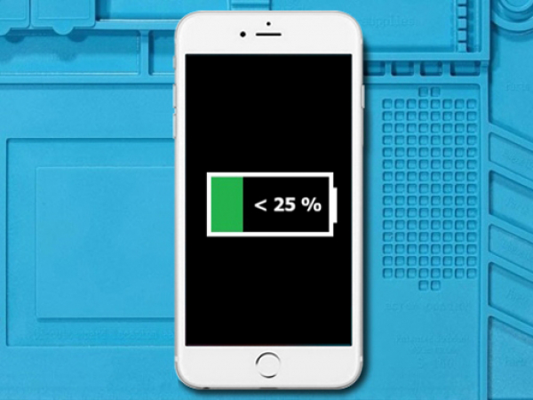


Step 1 - Discharge The Battery And Power Off The Phone
Power off your iPhone before you begin the disassembly.
Before you begin, discharge your iPhone battery below 25%. Lithium-ion batteries can catch fire and explode if accidentally punctured, especially with metal tools.
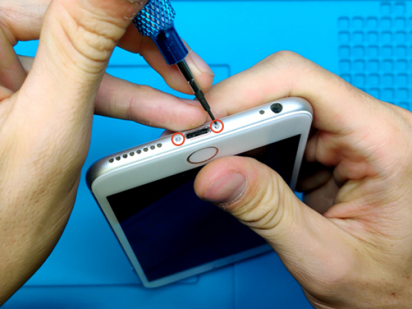


Step 2 - Opening Procedure
Back to top
Remove the two pentalobe screws (3.6 mm) on both sides of the Lightning connector.
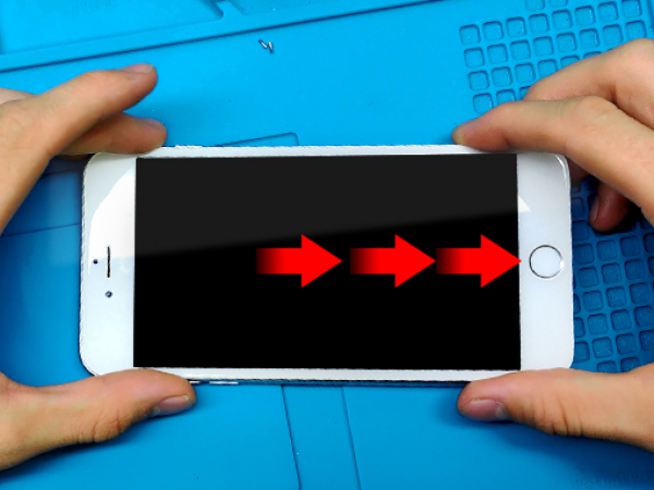
Slide in the flat metal opening tool between the display and the metal frame.
Start from the bottom part of the phone.
Twist the spudger to widen the gap between the display and rear case.
Advance alongside the right and the left edge until all the clips pop off.
Note:
Do not pry along the top edge of the phone, you risk damaging the plastic clips securing the display.
Tip 1:
If your display glass is shattered, prevent furhter glass breakage and injuries by taping over the glass.
Lay overlapping strips of clear self-adhesive tape over the phone's display until it is completely covered.
Tip 2:
Heating the lower edge of the iPhone will help soften the adhesive securing the display, which makes it easier to open.
Use a heatgun, or a hairdryer to apply heat to the lower edge of the iPhone for about a minute in order to soften up the adhesive underneath.


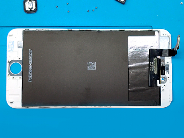
Step 3 - Lifting The Display
Back to top
Pull the bottom end of the front panel away from the metal case of the phone, using the top edge of the phone as a hinge.
Avoid pulling the display to more than 90º, and use something to prop it up against while you are working on the phone.
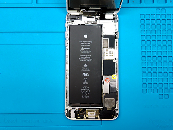


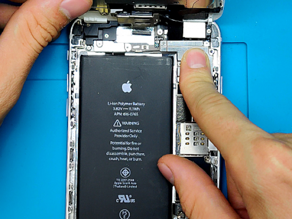
Step 4 - Battery Connector
Back to top
Remove one 2.3mm screw and one 3.1mm screw.
Remove the metal bracket that protects the battery connector.
Disconnect the battery with the edge of an opening tool or pry it gently with a clean fingernail.
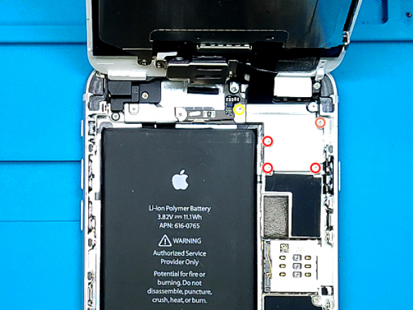


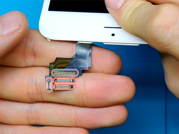
Step 5 - Front Panel Assembly Connectors
Back to top
Remove the five Phillips screws that secure the front panel assembly connector metal bracket:
3x 1.2mm screws
1x 1.5mm screw
1x 2.9mm screw
Remove the front panel assembly bracket.
Keep the LCD proped and supported at all times.
Again, use your fingernails or the edge of an opening tool to disconnect the front-facing camera connector.
Disconnect the earpiece speaker connector.
Disconnect the home button cable connector.
Disconnect the LCD cable connector.
Remove the front panel assembly from the phone's rear case.
Caution:
Sort the screws when removing them so you can put them back at their proper sockets.
Some screws are longer than others, and inserting them into the wrong wholes may cause an irreparable damage.
Note:
Pay attention that you pry up only on the cable connectors, and not on their sockets on the logic board.
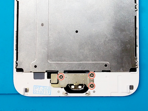


Step 6 - Home Button
Back to top
Use a Phillips screwdriver to remove three 1.8mm screws from the bottom part of the assembly.
Remove the metal bracket that secures the home button.
Disconnect the home button connector cable.
Carefully remove the home button/fingerprint scanner.
Note:
The Touch ID will ONLY work with your phone's original home button, so you'll need to transfer the home button from your old screen to your new screen.
Your replacement LCD may come with an extra Phillips screw already installed near the home button.
Remove that screw so that you can reinstall the home button and the bracket.
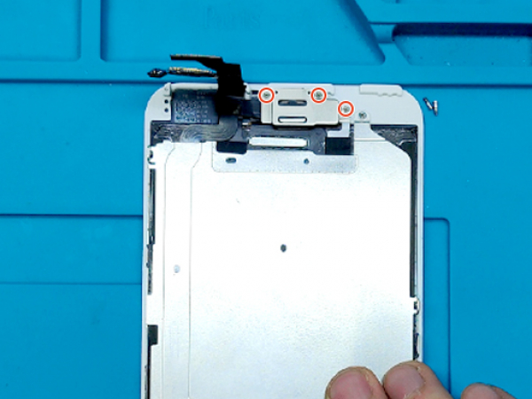


Step 7 - Earpiece
Back to top
Now remove the 3 screws from the top part of the assembly.
Remove the metal bracket of the earpiece, front camera and sensor array.
Remove the earpiece.
Remove the front camera and sensor array as a one piece.
Note:
Sensors and the camera come off as one piece.
Remove the earpiece mesh glued together with it.
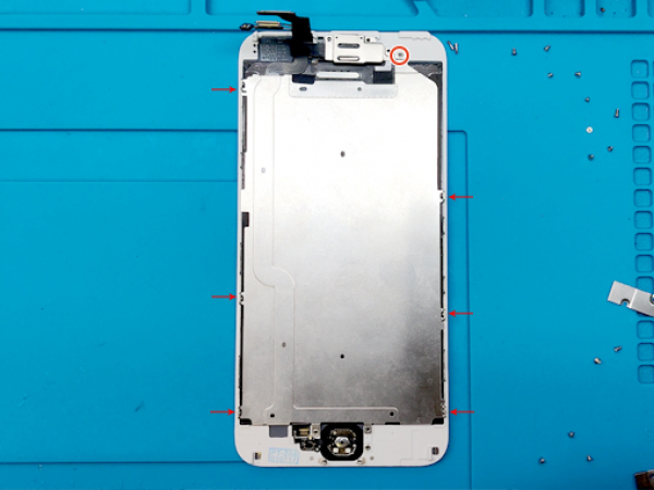


Step 8 - Metal Shield
Back to top
Your replacement front panel assembly may come without a metal shield.
The home button flat cable and both parts of the connectors are glued onto it.
You will need to transfer it from the old one.
Remove 6 screws, 3 on both sides of the assembly.
Remove one screw from the top.
Two screws from the bottom are already removed with the home button bracket.
Carefully unglue the homebutton connector with tweezers.
Now you can remove the shield with a home button cable attached to it.
Note:
Compare your original screen with the new replacement part.
Check which components you need to transfer before installing.


Step 9 - The Transfer
Back to top
Now take the new front panel assembly and install the metal shield you previously removed.
Align it with the back side of the assembly secure it with six side screws.
Glue down the bottom home button connector to the panel.
Insert the home button into the bottom hole and plug the connector in.
Place the metal bracket on top of it and secure it with three 1.8mm screws.
Now install the front camera, sensors and earpiece.
Place the bracket on top of the assembly and secure it with five screws you removed from the old panel.
Note:
Your replacement LCD may come with an extra screw installed left of the home button.
Remove that screw prior to reinstalling the home button bracket.


Step 10 - Connecting The New LCD
Back to top
It is time to connect the front panel to the logic board.
Connect the LCD cable connector.
Disconnect the home button cable connector.
Disconnect the earpiece speaker connector.
Connect the front-facing camera connector.
Reconnect the battery so you can test the phone.


Step 11 - Reassemble The Device
Back to top
Turn off your phone, disconnect the battery and lift the screen once more.
Keep the front panel propped at all times.
Install the metal bracket and secure it with five screws you removed at Step 5.
Reconnect the battery one final time.
Install the metal bracket and secure it with 2 screws removed in Step 4.
Now lower the front panel and pop in the clips starting with the top ones.
Gently press the edges of the screen and work your way down.
Finish off the repair with the two pentalobe screws (3.6 mm).