


iPhone 7 Home Button Replacement

Send this link via e-mail
|
Tweet |
|


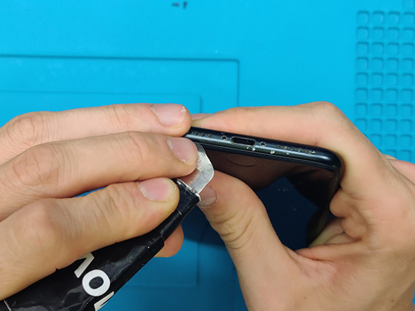
Step 1 - Pentalobe Screws
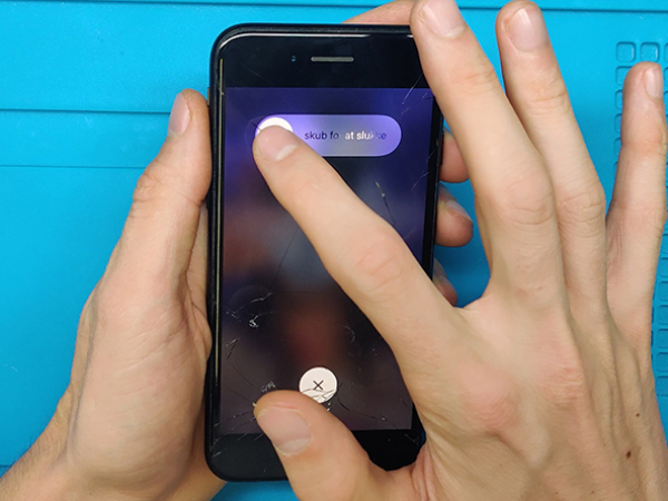
Turn off your device.
Remove the two 3.4 mm pentalobe screws on the bottom edge of the iPhone.
Before you start:
Most replacement parts won't work, so be sure to check carefully before you attempt the repair.
The iPhone's original Touch Id is uniquely paired to the mother board at the factory.
Without Apple's proprietary calibration, even a genuine replacement part from another iPhone will not work.
Install only a specially-made, universal-style home button.
Note that after the repair, the replacement button will only work as a button.
You will lose Touch ID functionality.
Note:
Opening the iPhone's display will compromise its waterproof seals
Have replacement seals ready before you proceed.
Take care to avoid liquid exposure if you reassemble your iPhone without replacing the seals.


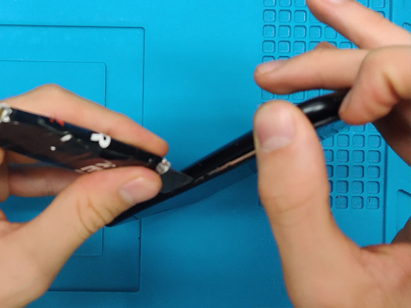
Step 2 - Opening Procedure
Back to top
Insert the flat end of a spudger into the gap.
The watertight adhesive holding the display in place is very strong, and creating this initial gap takes a significant amount of force.
If you're having a hard time opening a gap, rock the screen up and down to weaken the adhesive until you can fit a spudger inside.
Tip 1:
Heating the lower edge of the iPhone will help soften the adhesive securing the display, making it easier to open.
Use a heat gun (hair dryer) around the edges of the iPhone for about a minute in order to soften up the adhesive underneath.
Tip 2:
You can use a suction cup to help you lift the screen easier.
If your display glass is cracked, keep further breakage contained and prevent bodily harm during your repair by taping over the glass.


Step 3 - Opening Procedure II
Back to top
Slide the spudger edges of the iPhone starting from the bottom.
Twist the spudger to widen the gap between the display and rear case.
Do not start prying along the top edge of the phone, you risk damaging the plastic clips securing the display.
Pull the display assembly slightly away from the top edge of the phone to disengage the clips holding it to the rear case.
Open the iPhone by swinging the display up from the left side, like the back cover of a book.
Don't try to fully separate the display yet, as several fragile ribbon cables still connect it to the iPhone's logic board.
Attention:
Do not raise the display more than 10º as there are ribbon cables along the right edge of the device connecting the display to the logic board.
Step 4 - Disconnect The Battery & LCD Display I
Back to top
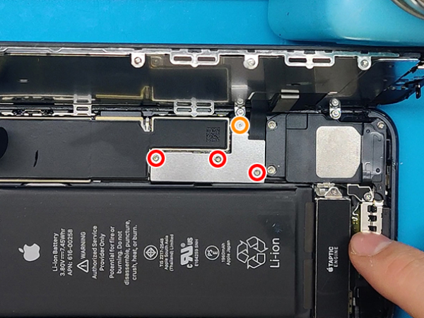
Remove four tri-point Y000 screws securing the lower connector bracket, of the following lengths:
Three 1.2 mm screws
One 2.4 mm screw
Tip:
Throughout this repair, keep track of each screw and make sure it goes back exactly where it came from to avoid damaging your iPhone.


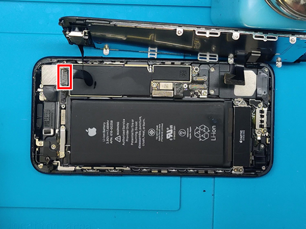
Step 5 - Disconnect The Battery & LCD Display II
Back to top
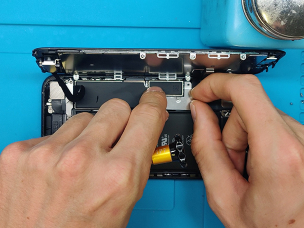
Remove the lower connector bracket.
Use the point of a spudger to lift the battery connector out of its socket on the logic board.
Bend the connector cable up slightly to prevent it from making contact with the socket and providing power to the phone.


Step 6 - Disconnect The Battery & LCD Display III
Back to top
Make sure the battery is disconnected before you disconnect or reconnect the cables in this step.
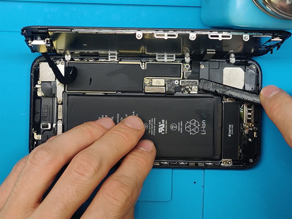
Use a spudger or a fingernail to disconnect the two lower display connectors by prying them straight up from their sockets on the logic board.
Remove the two 1.3 mm Phillips screws securing the bracket over the front panel sensor assembly connector.
Remove the bracket.
Disconnect the front panel sensor assembly connector from its socket on the logic board.
Remove the display assembly.
Note:
To reconnect these cables, press down one end until it clicks into place, then repeat on the opposite end. Do not press down in the middle. If the connector is even slightly misaligned, it can bend, causing permanent damage.
If you have a blank screen, white lines on the display, or partial or complete lack of touch response after reassembling your phone, try disconnecting and carefully reconnecting both of these cables and make sure they are fully seated.
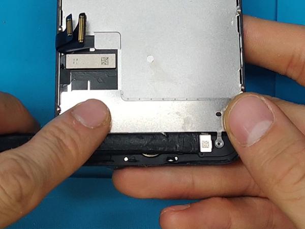
Step 7 - Home Button Bracket
Back to top
Once You successfuly removed the front panet you can put the rest of the phone aside.
Let's focus on the assembly and remove the Home Button.
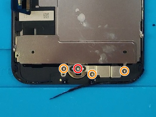
Remove all four of Y000 screws and the the bracket over the Home Button /Touch ID sensor:
- 1x 1.1 mm screw
- 3x 1.3 mm screws
Note:
When reassembling, do not overtighten these screws, or your Home Button may not function.


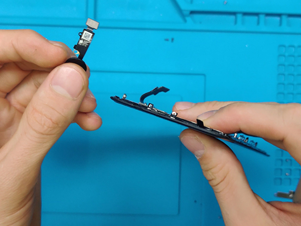
Step 8 - Unglue And Remove The Home Button
Back to top
Disconnect the flat cable connector using a tip of a nylon spudger.
Use a heatgun or a hair dryer to loosen the glue hodling the Home Button cable.
Heat up the area from the front of the LCD assembly.
Pry up the cable with a nylon spudger, plastic pick or siply use your fingers.
Then you gently press the Home Button, until it pops-of from the fron side of the panel.
Remove the button, the cable will go through the Home Button hole.


Step 9 - Installing The New Home Button
Back to top
Take the new Home Button and pull the cable throu the hole form the front side of the LCD.
Set the button in place.
There shuld be enough glue left from the old piece to hold the new flat cable glued down to the assembly.
Connect the Home Button connector with the socket on the LCD assembly.
Put the metal bracket over it and secure it with the 4 screws you remmoved in step 8.
Note:
Your replacement Home Button / Touch ID sensor may come with an extra screw already installed right of the Home Button.
Remove that screw and then reinstall the Home Button bracket.