


iPhone 7 Plus Screen Replacement

Send this link via e-mail
|
Tweet |
|
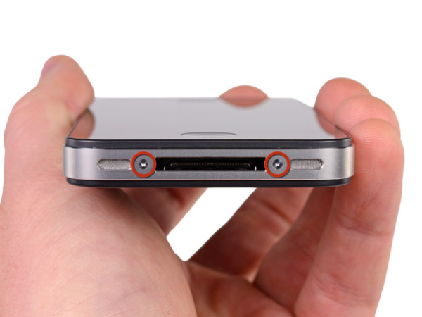
Step 1 - Rear Panel
Prior to disassembling your iPhone, make sure to turn it off.
Two 3.6 mm Pentalobe screws next to the dock connector need to be removed
While assembling the phone again, we suggest you to replace the 5-point screws with equivalent Phillips screws.
The 5-Point Screwdriver is meant to be used only once, as it may strip the screws.


Step 2
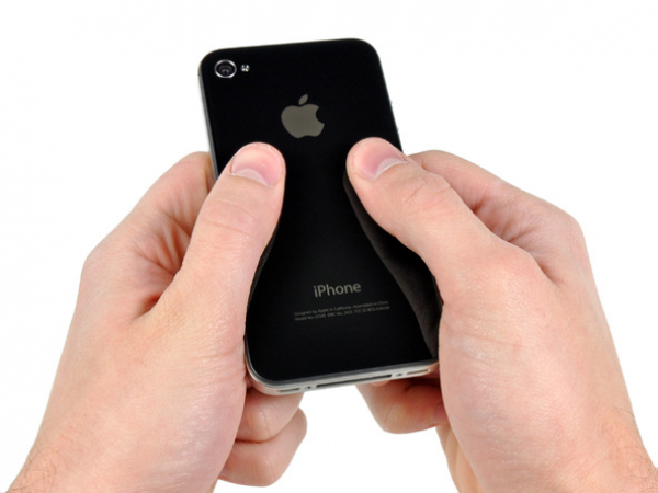
Press the back panel and push it towards the top edge of the iPhone.
Back panel will move about 2 mm.
Step 3
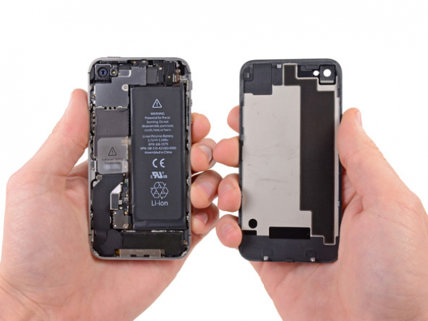
Separate the back panel from the back of the iPhone, and make sure not to damage the plastic clips fixed to the back panel.
Remove the back panel from the iPhone.
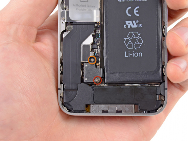
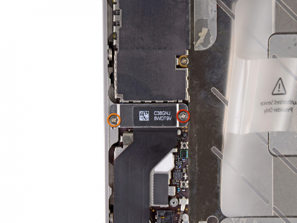
Step 4 - Battery
Back to top
These screws securing the battery connector to the logic board need to be carefully removed:
One 1.7 mm Phillips screw
One 1.5 mm Phillips screw


Step 5
With a help of plastic opening tool, you need to pull the pressure contact which is positioned below the battery connector.
When the pressure contact is being reinstalled, it needs to be cleaned with a degreaser such as windex or isopropyl alcohol. The natural oils on your fingers may accidentally create wireless interference.
Carefully separate the battery connector from its socket on the logic board by using the edge of a plastic opening tool.
Make sure only to raise the battery connector and not the connector on the logic board. If you push the logic board connector, it may happen to completely break the connector.
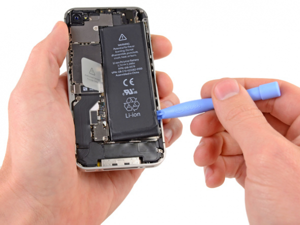


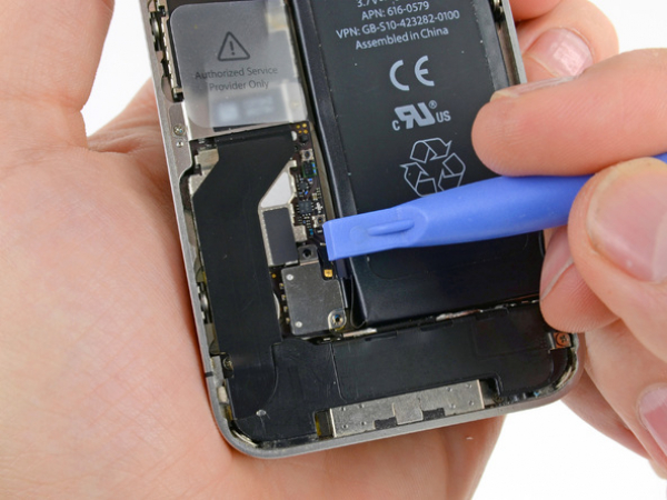
Step 6
Place the edge of a plastic opening tool between the battery and the outer case close to the lower left corner of the iPhone.
Move the plastic opening tool along the right edge of the battery and gently push at several points to entirely separate it from the adhesive securing it to the outer case.
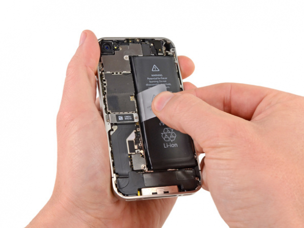


Step 7
Exposed clear plastic pull tab will allow you to peel the battery off the adhesive securing it to the iPhone.
Remove the battery.


Step 8 - Dock Connector Cable
Back to top
You have to remove two Philips screws that are connecting the dock cable cover with the logic board:
1.5 mm Phillips screw (1 piece)
1.2 mm Phillips screw (1 piece)
After taking the screws out, you can remove the metal cable cover.
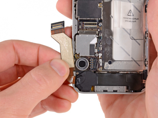
Step 10
You need to separate the dock cable from the adhesive that is securing it to the board and the side of the speaker area.


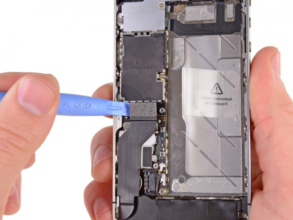
Step 11
With the edge of the opening tool lever the cellular antenna cable from its socket on the logic board.
Disconnect the cellular antenna cable from the metal joints attached to the board.
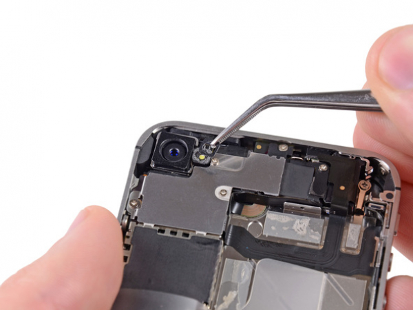
Step 12 - Back Camera
Back to top
To remove the outer plastic ring from the top of the back camera's flash, you can use a pair of tweezers or our opening tool.
Step 13
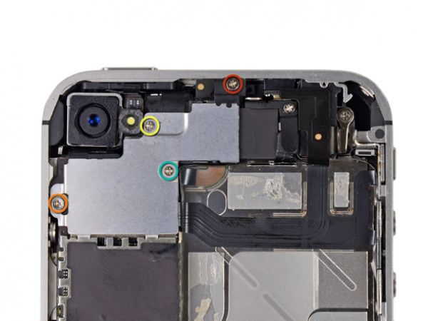
You have to remove the following four Phillips screws that are connecting the cable cover with the logic board:
2.7 mm Phillips screw (1 piece)
2.6 mm Phillips screw (1 piece)
1.3 mm Phillips screw (1 piece)
1.2 mm Phillips screw (1 piece)


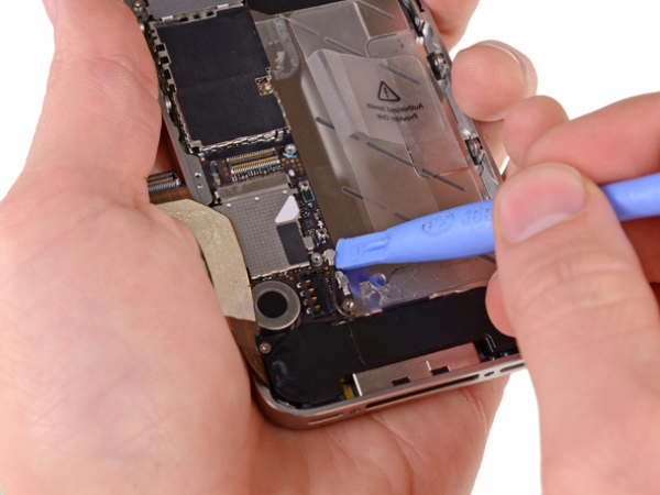
Step 14
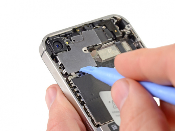
With the edge of the opening tool lever the cable cover tabs from their slots that are cut into the EMI shield on the logic board.
Move the cable cover upwards from its edge closest to the top and remove it from the iPhone.


Step 15
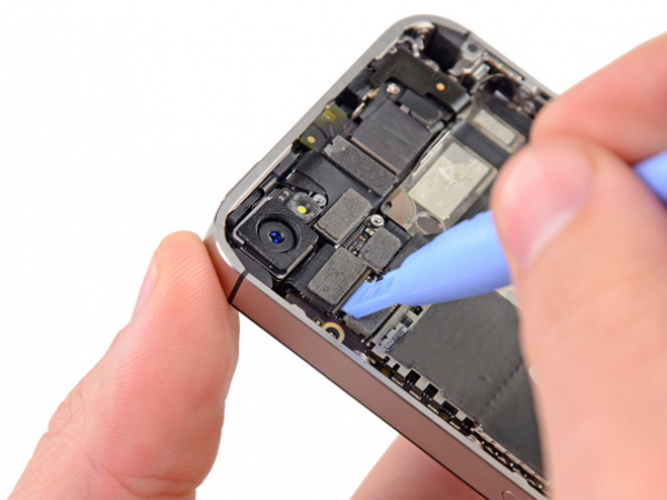
With the edge of a plastic tool lever the back camera connector from its slot on the logic board.
Lever the components from the logic board very carefully so as not to damage any of them.
Remove the back camera from the iPhone.
You will notice a small rubber cord underneath the back camera. Check whether it is placed properly before reassembly.