


iPhone XR Screen Replacement

Send this link via e-mail
|
Tweet |
|
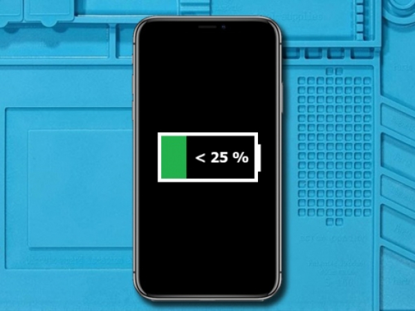
Step 1 - Before You Start
Before you start with the repair, the battery should be discharged below 25%.
If a Li-Ion battery is charged, it can catch fire or explode if punctured.
Caution:
If the battery is swollen, take adequate measures and precautions.
Do not heat your phone. You can use isopropyl alcohol around the edges of the back cover to weaken the adhesive
Wear eye and hand protection when working with swollen batteries.


Step 2 - Pentalobe Screws
Back to top
Turn your iPhone off.
Remove two 6.7mm pentalobe screws found at the bottom of your iPhone.
Note:
Opening the phone's display will endanger its waterproof features.
Make sure you have prepared the replacement seals before you continue with the repair.
Otherwise, avoid exposure to liquid if you reassemble your iPhone and not replace the seals.
Step 3 - Taping Over The Display
Back to top
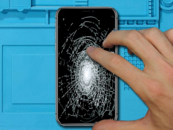
If the glass of display is cracked, prevent further tear by taping the glass over it.
Stick overlapping strips of transparent packing tape over the entire iPhone's display.
This keeps glass shards together and provide the integral structure while you pry and lift the display.
Note:
If your iPhone's display glass is not shattered, you can skip the entire Step 3
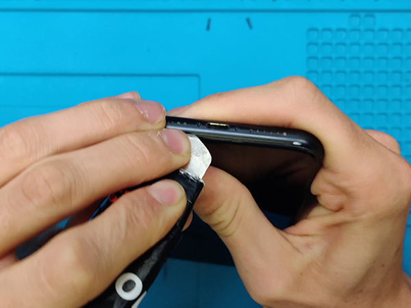


Step 4 - Opening Procedure
Back to top
Slide the spudger into the edges of the iPhone starting from the bottom.
Increase the gap between the display and back case by twisting the spurger.
Prying along the top edge of the phone may cause damage of plastic clips which secure the display.
Pull the display assembly slightly away from the top edge of the phone to disengage the clips holding it to the rear case.
Swing the display up from the left to open the device, like a book's back cover.
It is still not the time to completely detach the display, since a few fragile ribbon cables connect it to the iPhone's mother board.
Attention:
Lifting the display higher than 10º can damage the ribbon cables at the phone's right edge which connect the display to the logic board.
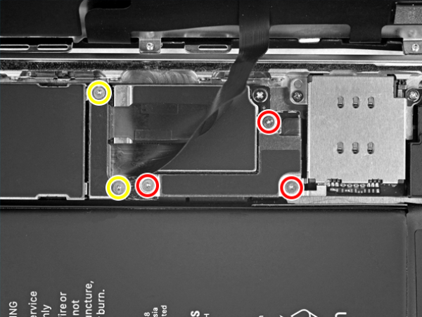
Step 5 - Disconnect The Battery & LCD Display I
Back to top
Remove five screws which secure the connector bracket of the logic board.
3x 1.2 mm Y000
1x 1.3 mm Phillips #000
1x 1.5 mm Phillips #000
Tip:
Keep track of each screw so you can put them back where they came from to avoid damaging your iPhone.
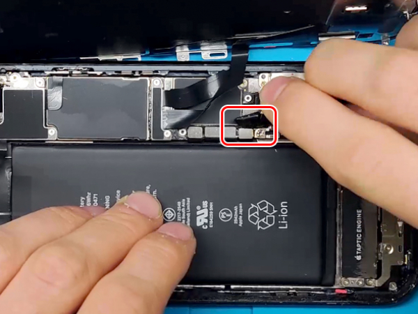


Step 6 - Disconnect The Battery & LCD Display II
Back to top
Remove the two connector brackets gently.
The spudger's point can help you lift the battery connector from its socket.
Bending the connector cable slightly upwards prevents the contaction with the socket and power in the phone.
Use the point of a spudger to pry the digitizer cable connector up.
Caution:
When reconnecting these cables, press down one end of the connector until it clicks back into place, then repeat on the opposite end.
Avoid pressing down in the middle. A misaligned connector can cause the pins to bend.
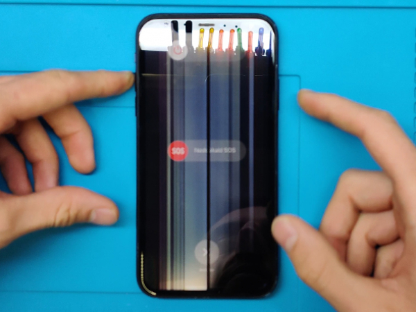
Note:
If the screen is blank, white lines appear or the display is partially / completely irresponsive to touch after reassemby, disconnect and carefully reconnect these two cables back into the right place.
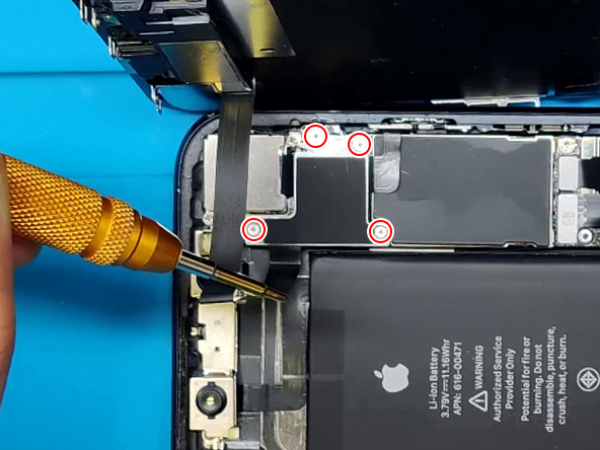


Step 7 - Disconnect The Battery & LCD Display IIII
Back to top
Remove the five screws of the the logic board connector bracket:
One 1.3 mm Phillips #000 screw
One 1.5 mm Phillips #000 screw
Three 1.2 mm Y000 screws
Remove the bracket
Pry the sensor assembly connector at the front out of its socket using the tip of a spudger.
The display should now be removed.


Step 8 - Sensor Assembly & The Earpiece I
Back to top
Remove the four screws which secure the sensor assembly & speaker to the back of the display:
2x 1.6 mm Phillips screws
1x 2.3 mm Phillips screw
1x 1.2 mm Y000 screw
Use a spudger to pry carefully under the upper edge of the assembly, and flip it - down and away from the display's edge.


Step 9 - Sensor Assembly & The Earpiece II
Back to top
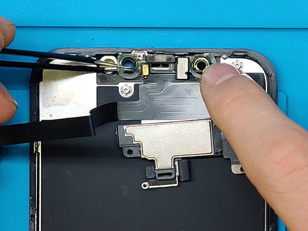
Slide an opening pick or tweezers left to right under the proximity sensor and flood illuminator module.
Slightly wiggle and lift to remove the module from its cavity in the front panel.
Remove the earpiece speaker and front sensor assembly.
Note:
If the ambient sensor came out with the white diffuser strip, separate it from the strip with a blade or pry tool.
Caution:
The ambient sensor is connected with the rest of the sensor assembly with a thin flex cable. Do not damage this cable.


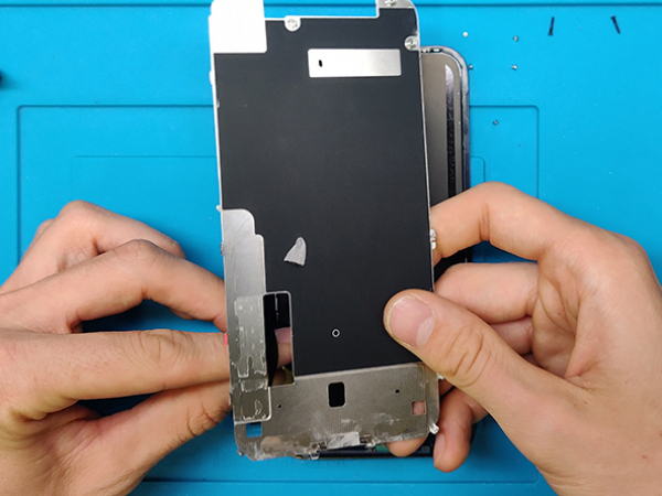
Step 10 - Metal Shield
Back to top
Note:
The new LCD we are using for this repair comes without the shield. You have to transfer it from the old one.
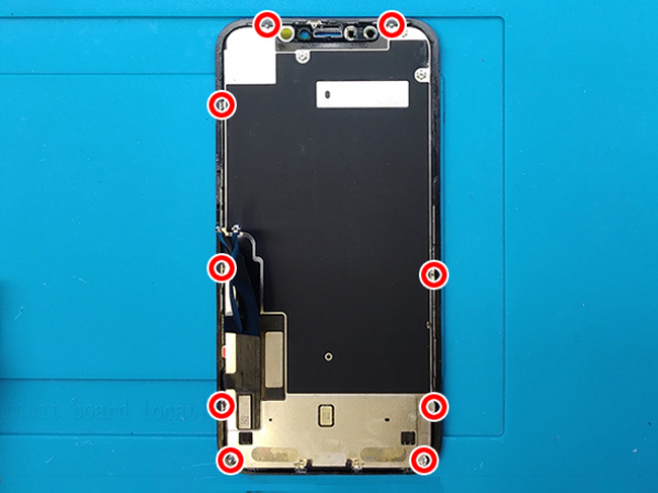
On the back of the display there is a metal shield.
Remove 9 screws in total from the LCD clips.
The side flex cable is adhered to the metal shield.
You will have to tear the flex cable away from the shield.
Now lift the shield from the top and pull and wiggle slightly so it unclips from the LCD panel.


Step 11 - New LCD I
Back to top
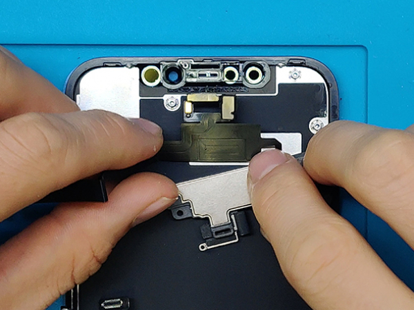
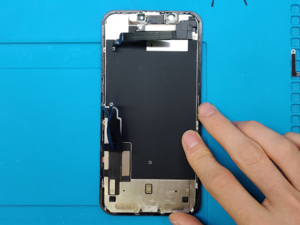
There is a pull tab on the bottom left side at the back of the new LCD.
Gently press the connectors with your fingers like shown in the photos.
Pull the tab to remove the adhesive strip.
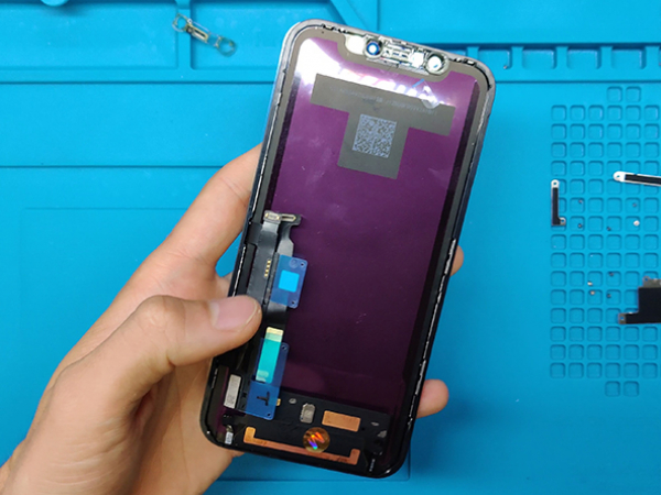
Now remove the protective film from the back of the display.
Slide the bottom flex cable throug the opening in the metal shield.
Flip over the side flex cables away from the LCD.


Step 12 - New LCD II
Back to top
Now install the metal shield starting with the bottom clips.
Make sure everything is aligned.
Remove the protective foil from the side flex to uncover the glue.
Now adhere the cable to the metal shield.
Install the 9 screws you removed from the old LCD and secure the shield to the new LCD.