


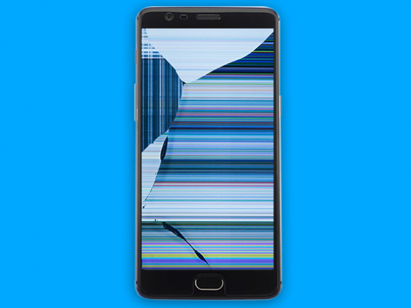
OnePlus 3 Screen Replacement

Send this link via e-mail
|
Tweet |
|


Step 1 - Before You Start
- Discharge the battery bellow 25%.
- Turn off your OnePlus 3.
- Remove the SIM card using a SIM eject tool, or a straightened paperclip.
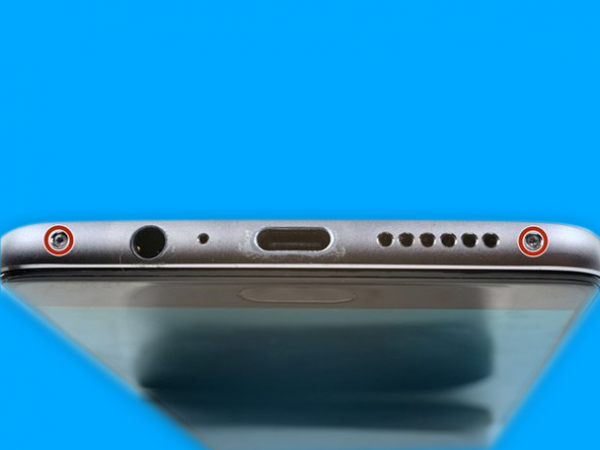


Step 2 - Removing The Back Cover
Back to top
- Start with removing 2x 2.6mm T2 screws from the bottom.
- The screen and the body are joined by two different seams:
- Display panel seam and frame seam.
- Avoid prying at the display panel seam, you can damage the panel.
- Pry at the frame seam where the plastic meets the frame.
- 14 clips fasten the frame to the rear case.
- Locate them and carefully proceed with the back cover removal.
- Put a suction cup at the bottom of the display.
- With enough force, use the suction cup too slightly to lift the display off the frame.
- Insert the plastic opening tool into the seam below the suction cup.
- Ensure that the opening is wedged between the display panel frame and the cover's lip.
- Slip the tool into the phone's bottom edge and slide along carefully around the left corner. Keep the tool's edge in the seam at all times.
- Keep sliding the tool along the left side of the phone, releasing the clips.
- The last clip is near the alert switch in the upper left corner.
- It is placed a bit deep, so it can be difficult to release.
- Proceed slowly using an opening pick or the flat end of a tool to help you.
- Once the bottom and the left edge of the device are free, tilt the frame gently to release the right and the top clips.
- Remove the screen off the frame by lifting it up.
Caution:
- There is a high risk of damaging the display, so follow the opening procedure properly.
Tip:
- Try not to accidentally power on the phone. In case you do, turn it off and resume the disassembly.
- Do not use metal when removing the display, there is a risk of cracking the screen.
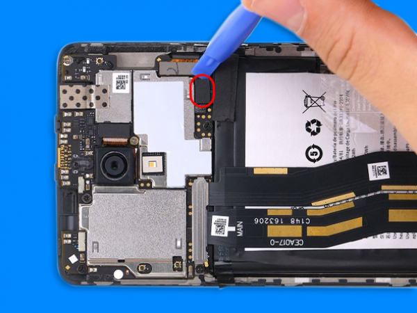


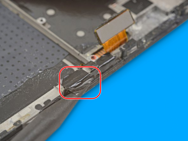
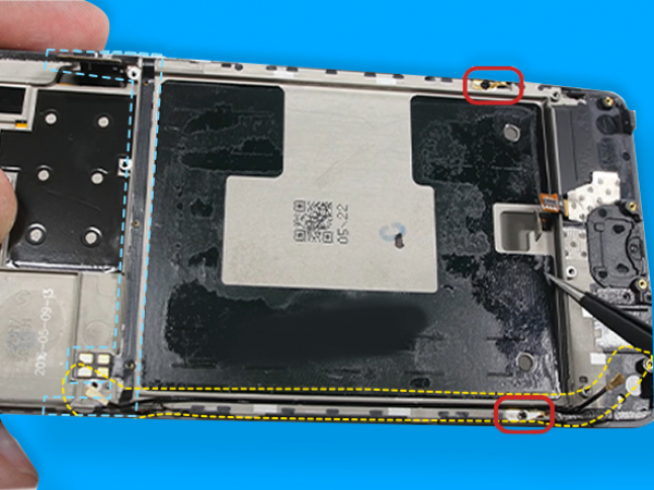
Step 3 - Removing The Battery
Back to top
- With the tip of a spudger pry the connector up from its socket to disconnect the battery.
- Bend the connector away to prevent accidental contact with the socket.
- Unscrew and remove the 3mm Phillips screw securing the metal bracket.
- Remove the cable bracket to expose the connectors.
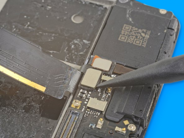
- Disconnect the interconnect flex cable using the point of a spudger. Do the same with the daughterboard flex cable and the motherboard.
- At the bottom of the phone, below the battery, separate the interconnect flex cable from the daughterboard.
- Once the interconnect flex cable is removed, carefully bend the daughterboard flex cable which is still attached away from the phone's battery.
- There should be adhesive tapes holding the battery to the edges of the plastic frame.
- Use the plastic opening tool to push them off the battery.
- There is also the transparent pull foil to peel from the battery.
- Hold the phone frame firmly against the table.
- Lift the transparent foil tab with force until the battery loosens from its opening.
- Be advised that the adhesive is very strong, so you need to use solid and steady force to remove the battery.
- Swing the battery out of its cavity, and remove any remaining adhesive.
Caution:
- Be careful not to puncture the battery, especially with a metal tool.
Tip:
- You can apply some high concentration isopropyl alcohol along the battery seam to weaken the adhesive.
Note:
- If the battery is bent or otherwise damaged, you should use a new battery, due to potential safety hazards - Wear eye and hand protection.


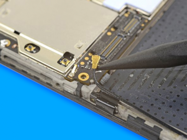
Step 4 - Removing The Daughterboard
Back to top
- The capacitative button connector should be disconnected from the daughterboard. - Then disconnect the connector for the fingerprint scanner as well.
- With the point of a spudger disconnect the antenna from the daughterboard.
- Remove 7x Phillips screws which secure the daughterboard:
- 2x 3mm screws (black),
- 5x 2.9mm screws (silver).
- Insert the spudger's flat end under the loudspeaker and twist it gently until the daughterboard releases itself from the two side clips.
- Now you can remove the daughterboard from the phone frame.


Step 5 - Removing The Fingerprint Scanner
Back to top
- Insert the edge of the tool under the fingerprint scanner cover near the device's bottom edge.
- Pry the fingerprint scanner up and remove it.
- Firmly push the fingerprint scanner with your finger from the display front.
- The scanner should dislodge from the cutout, so you can peel it off the frame together with its tape.
- Remove the scanner.


Step 6 - Removing The Motherboard
Back to top
- Disconnect the anntena cable from the motherboard.
- Pry to separate the display connector and the motherboard.
- Remove 7x Phillips screws for the motherboard:
- 4x 3mm screws (black),
- 3x 2.9mm screws (silver).
- Some screws may have stickers over them, remove them so you can access the screws.
- You can see clips near the top still holding the motherboard in place.
- Insert the flat end of the tool under the upper left corner of the motherboard.
- Twist the spudger up until you free the motherboard.
- The motherboard can now be removed.
Note:
- Doublecheck if you have ejected and removed the SIM tray before attempting to remove the motherboard.


Step 7 - Removing The Power And Volume Button Assembly
Back to top
- Remove the black tape which covers the volume buttons on the right and the power button on the left.
- Use the spudger's flat end to separate the volume button board from the frame gently.
- Use the tool to loosen the power button from the frame's left edge by prying.
- Insert the point under the rectangular contact pad with tweezers, then pry and loosen it.
- Lift the volume flex cable to remove it from its groove.
- Since you loosened the contact pad now you can remove it along with the volume and power button.
Tip:
- You can reuse the back tape pieces so try not to tear them.
- But, no worry, you can use electrical tape.Caution:
-If the volume button board bends significantly, stop immediately and pry from a different angle.
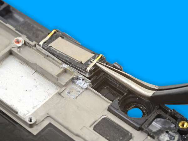


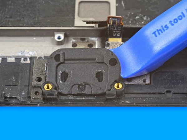
Step 8 - Removing The Earpiece Speaker, Antenna And Ground Clips
Back to top
- Using the tweezer tips under one of the earpiece speaker clips you can pry to remove the earpiece.
- Pry up slowly to remove the earpiece speaker.
- Remove the earpiece speaker.
- Remove 2x 1.9mm Phillips screws holding the frame grounding clips.
- Remove the two frame grounding clips to transfer them to the new LCD assembly.
Caution:
-If the earpiece speaker clip starts to bend upwards, stop and try with another clip.
Note:
- The ground clips are directional so make sure to install them correctly.


Step 9 - Reassembly
Back to top
- Reassembly is pretty straightforward, almost reversing the disassembly process.
- You should start transferring the parts previously removed from the old assembly.
- Start with the ground contacts and then proceed with the antenna cable.
- Install the volume button and power button flex,
- Install the ear speaker,
- Install the motherboard,
- Install the daughterboard,
- The battery is next to be installed,
- After the battery is installed, you can reconnect the flex cables to the motherboard and secure the connectors with the bracket.
- At the end, you connect the battery.
- Install the back cover and secure it with the two 2.6mm T2 screws.
- Insert the sim tray, and you can power on your device.
- And your repair is done.