


Samsung Galaxy A51 Screen Replacement

Send this link via e-mail
|
Tweet |
|


Step 1 - Warm Up The Glue
Make sure to turn off your Samsung Galaxy A51.
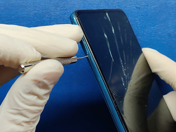
Insert a tool for ejecting the SIM card or a paper clip into the hole on the SIM tray at the left side of your phone.
Eject and remove the tray.
We are using a hot plate machine at 90°C-100°C to loosen the glue. (not shown)
You can use a heat gun or a hairdryer to heat up the backside of the phone.


Step 2 - Removing The Back Cover
Back to top
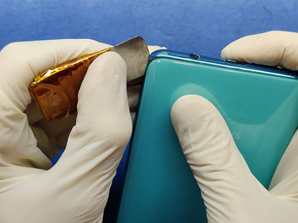
Insert the thin metal opening tool between the metal frame and the back cover of the phone.
Start from the bottom and go all around the edges to cut through the glue.
There are no cables attached to the back cover but avoid inserting the iFlex tool more than 1cm.
Remove the back cover.


Step 3 - Midframe
Back to top
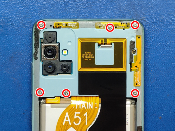
Remove the thirteen 3mm Phillips #00 screws which secure the phone's midframe.
6 screws from the top part, 7 screws from the bottom.
Plastic clips hold the midframe in place.
Insert the opening tool between the midframe and the front panel assembly on the bottom to release the bottom clips.
Insert and slide the opening tool along the right side of the phone to release all plastic clips on that side.
Repeat the same on the left side of the phone.
In the same manner, release the plastic clips from the top part of the phone.
Remove the midframe.


Step 4 - Disconnect The Battery And The LCD
Back to top
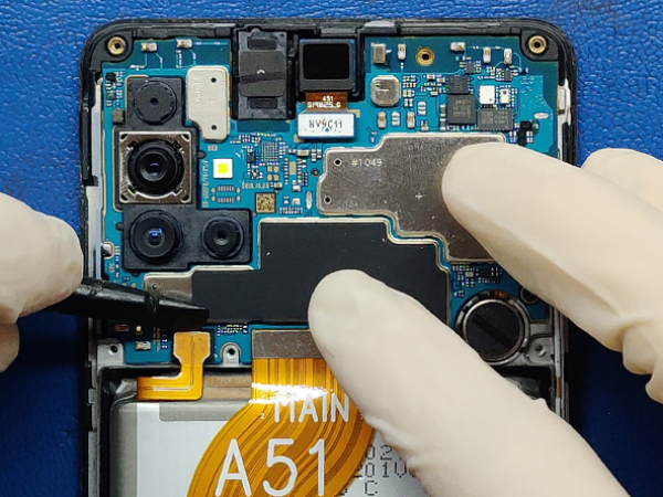
Use the flat end of a spudger for prying the battery connector straight up from its socket.
Using the flat end of a plastic spudger pry up and disconnect the display flex cable
Remove the single near that secures the motherboard, near the vibration motor.
Remove two screws from the bottom which secure the fingerprint sensor.


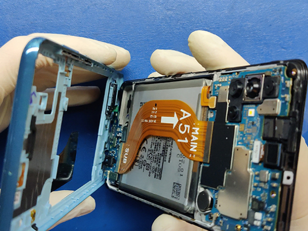
Step 5 - Removing The Parts
Back to top
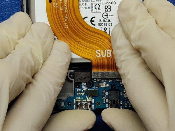
Now you can remove the MAIN board (motherboard) and SUB board (lower board), in one step.
They should come off with all other parts like the fingerprint sensor and cameras.
The SUB board is secured with some glue so pull it up carefully.
Also, pay attention to the antenna and flex cables that connect MAIN and SUB board.


Step 6 - Transferring The Battery And The Speaker
Back to top
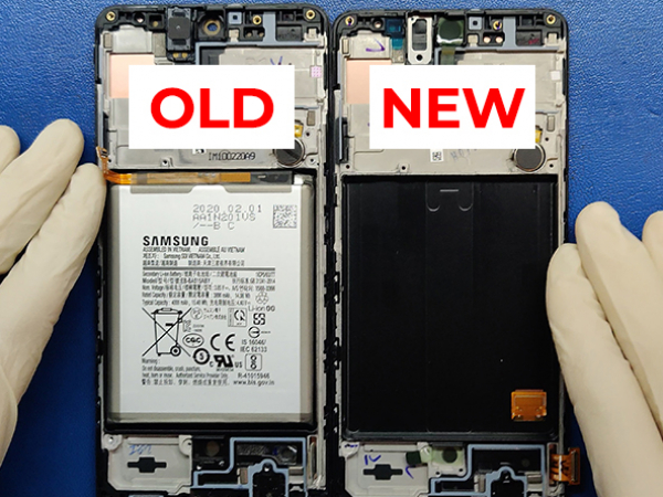
Comparing the new and the old LCD assembly we found out that we have to transfer the battery and the speaker.
Use isopropyl alchohol to dissolve the glue under the battery.
Carefully remove the battery and avoid using sharp tools so you don't puncture the battery.
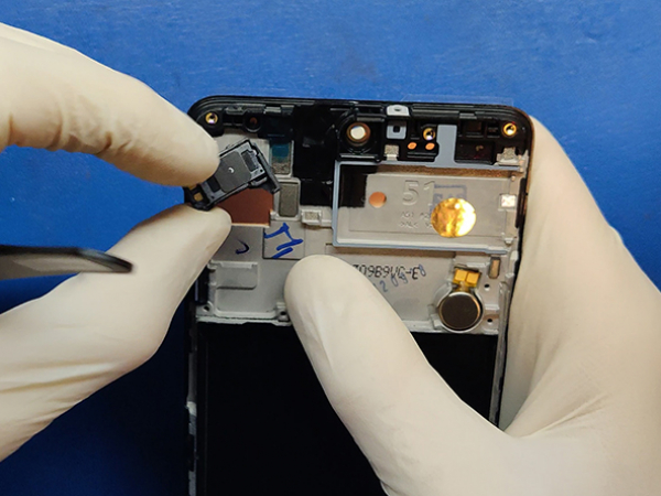
Use your tweezers to pry the speaker out of the old LCD assembly.


Step 7 - Transferring The Battery And The Speaker
Back to top
Install the speaker and the battery into the new LCD assembly.
Use two pieces of double-sided self-adhesive tape to secure the battery.


Step 8 - Installing The Main And The SUB Board
Back to top
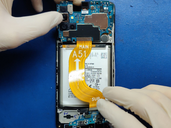
Install the MAIN and the SUB board in the new LCD assembly, the same way you removed them from the old one.
Yet again pay attention to the fragile cables and connectors.
Secure the fingerprintscanner with the two screws you previously removed.
Secure the motherboard with the screw you've removed earlier.
Tuck in the antenna cable.
Connect the LCD flex to the SUB board connector.
Connect the battery cable to the MAIN board connector.


Step 9 - Midframe And Back Cover
Back to top
Install the midframe and secure it with 13 screws you removed in STEP 3.
Remove the old glue residue from the frame.
Add doube-sided adhesive tape all around the frame.
Place the back cover on top and press with your fingers along the edges.
Turn on your device and enjoy.