Design Your Own Case FOR MOBILE OR TABLET! CLICK HERE


Samsung Galaxy A70 Screen Replacement

Send this link via e-mail
|
Tweet |
|


Step 1 - Rear Case
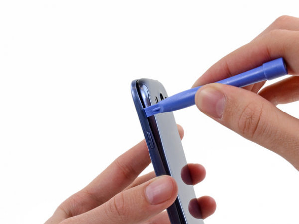
It is recommended to use a plastic tool for opening the rear case in the next four steps in order to avoid damaging of the clips along the perimeter of the case.
On the top part of the unit, in the notch where the rear case and the rest of the phone connect, insert the plastic or any other slim tool.
Carefully twist the tool until the clips disconnect.


Step 2
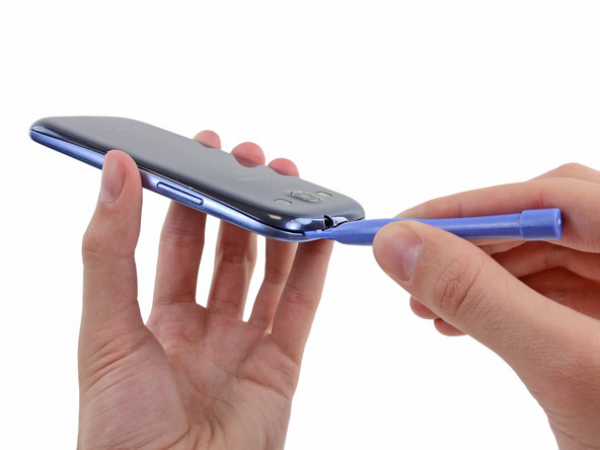
Once again insert the tool from the left top side and continue with gentle twisting of the tool so the the gap can widen up.


Step 3
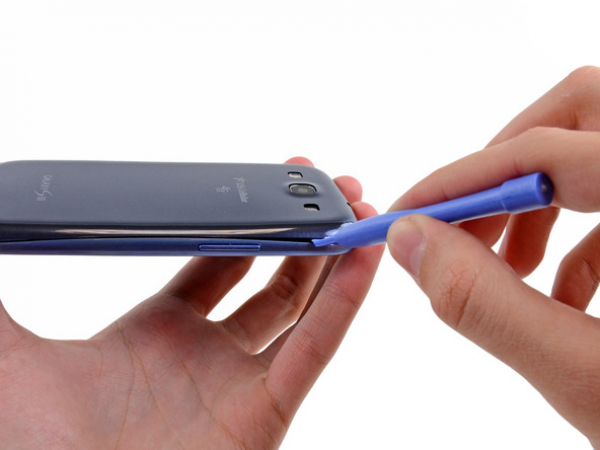
Continue to move the plastic opening tool around the perimeter of the top left corner, gently prying up along the rear case.