


Samsung Galaxy S8 Screen Replacement

Send this link via e-mail
|
Tweet |
|


Step 1 - Warm Up The Glue
Switch off your Samsung Galaxy A70.
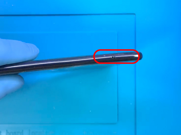
Eject and remove the tray, you can use a simple paper clip if you do not have the tool.
Apply heat along the edges at the back of the phone to soften the adhesive which holds the back glass.
Use a heat gun or a hair dryer for a minute or so at max. 110°C.
You may need to repeat the process because the glue hardens quickly.


Step 2 - Removing The Back Cover
Back to top
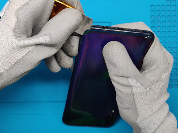
Starting from the bottom, insert the thin metal opening tool between the metal frame and the back cover of the phone.
You can go all around the edges to cut through the glue.
Remove the back cover.
The back cover of this device is plastic so there is a minimal chance of braking it.


Step 3 - Midframe
Back to top
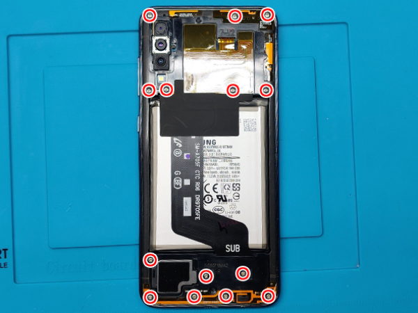
Remove a total of fourteen Phillips #00 screws that secure the phone's midframe.
7 screws from the top part and 7 screws from the bottom.
Plastic clips hold the midframe in place.
Insert the thin opening tool or a plastick pick between the display and the midframe at the bottom of your phone.
Slide the tool along the bottom edge to release the clips.
Continue sliding the tool along the left edge of the phone to release the clips.
Make sure you free all the clips securing the midframe.
Separate the midframe from the phone.


Step 4 - Disconnect The Battery And The LCD
Back to top
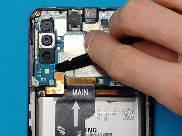
Use the flat end of a spudger for prying the battery connector.
Remove the single screw that secures the motherboard, near the vibration motor.
Remove two screws from the bottom which secure the fingerprint sensor.
Disconnect and remove the fingerprint sensor.
Disconnect the display flex cable.


Step 5 - Removing The Parts
Back to top
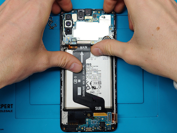
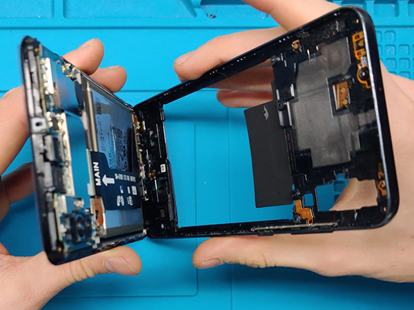
You can now remove the MAIN board (motherboard) and SUB board (lower board).
Pay attention to the thin antenna cable and flex cables that connect the MAIN and the SUB board.
The SUB board is secured with some glue so pull it up carefully.


Step 6 - Transferring The Battery And The Speaker I
Back to top
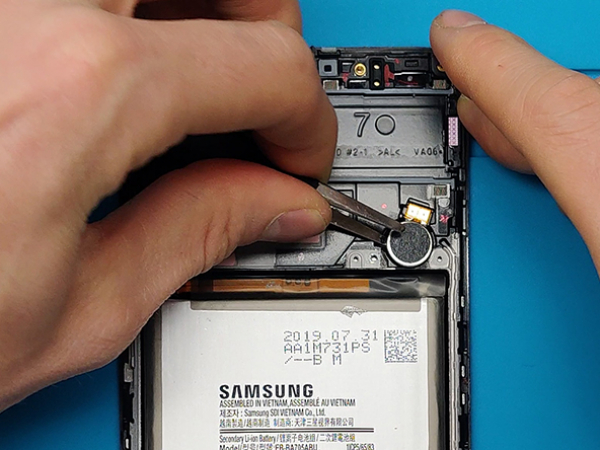
Comparing the new and the old LCD assembly we found out that we have to transfer the speaker, the vibration motor and the battery.
First two come off pretty straight forward, just use tweezers to pry the speaker and the vibra motor out of the old LCD assembly.
For the battery, use isopropyl alchohol to dissolve the glue under the battery.
Samsung is pretty generous with the glue so you may need to heat the device once again.
Carefully remove the battery and avoid using sharp tools so you don't puncture the battery.


Step 7 - Transferring The Battery And The Speaker II
Back to top
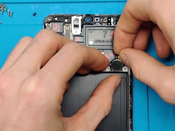
Install the speaker and the vibra motor into the new LCD assembly.
Clean up any remaining adhesive from the battery
Then, set two pieces of double-sided self-adhesive tape to secure the battery.


Step 8 - Installing The Main And The Sub Board
Back to top
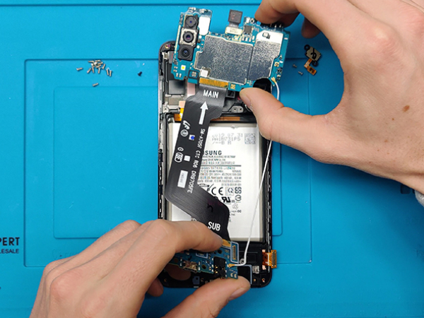
Install the MAIN and the SUB board in the new LCD assembly, the same way you removed them from the old one.
Yet again pay attention to the fragile cables and connectors.
Tuck in the antenna cable.
Secure the fingerprintscanner with the two screws you previously removed.
Secure the motherboard with the screw you've removed earlier.
Connect the LCD flex to the SUB board connector.
Connect the battery cable to the MAIN board connector.


Step 9 - Midframe And Back Cover
Back to top
Install the midframe and secure it with 14 Phillips #00 screws.
The adhesive tape on the back cover we removed is in good shape, so we will not use other adhesive.
If your situation is different you can use doublesided tape.
Place the back cover on top and press with your fingers along the edges.
Apply strong, steady pressure to your phone for several minutes.
A stack of heavy books on top of the phone can help the adhesive form a good bond.
Turn on the device and enjoy.